26 August 2013

Go Go Turbo Lens,,,,,,

In a break from my usual ramblings about CGI, I bought a new toy for my camera the other week and figured I'd write about it because a) it's pretty neat and b) it does tie in with my CGI work in a way as I use this camera for all of the live action in my composite testing & experiments.

The new toy I mentioned is a "Lens Turbo" from Zhongyi, not one of the best known manufacturers of camera optics in the world but hey, they had a neat idea and got to market with a competitive product that caught my eye.


The Lens Turbo is an adapter that converts the e-mount fitting on my NEX 5N to M42 thread mount which means that I can attach old, well built, manual m42 lenses to my camera body and reap the benefits of using quality glass at a fraction of the cost.

Now, I've been using various adapters for my 5N since I got the body but the difference with the Lens Turbo is that it is not a simple tube like my other "dumb" adapters but has it's own optics which lessens the crop factor of the sensor in the camera.

OK, so I should probably explain crop factor now.......

Most lenses are built with 35mm film in mind, this means that the light is focussed down to the approximate area of a frame of 35mm film or a full frame sensor in a digital camera (36 x 24mm). So if you're using the lens on a camera with a smaller than full frame sensor it will result in the image being cropped because only the light that hits the sensor is processed.

The image above illustrates crop factor nicely. The blue rectangle is equivalent to the size a full frame sensor or 35mm film and the black rectangle is equivalent to the APS-C sensor in my NEX 5N, which has an approximate crop of 1.5 meaning that a full frame sensor is about one and a half times it's size. 

The white area represents the light that is cast by any lens and the grey area represents the light which is processed by my crop sensor for that lens. It's easy to deduce from the image that the field of view has been drastically reduced and that, while it would be possible to get the same field of view by taking a picture from a position further back, the depth of field in the shot would be affected as the lens would need to be refocussed.

The Lens Turbo refocusses the light from any attached lens onto the area of the APS-C sensor in my camera reducing the crop factor to a negligible amount. In some tests in which I compared a 50mm lens on one of the full frame Canon 5D mkIII's at work against my 50mm Super Takumar with the Lens Turbo the crop factor was reduced to approximately 1.08 which is a significant step up from the original 1.5.

The two images in this GIF were shot in my local park from the same spot on a tripod, and using the same 50mm lens. One with the dumb adapter and the other with the Lens Turbo, I scaled the dumb adapter image down to better illustrate the crop.......


The images were shot in wide screen format as I usually use my camera for video work and forgot to change the settings but as this is simply a demonstration of the adjusted field of view that the Lens Turbo offers, and not an entry in a photography competition I figured it would be ok in this case.

Another benefit of the Lens Turbo is that because more light is focussed onto the sensor the aperture is effectively reduced by nearly a whole stop so my 1:1.4 50mm Super Takumar is opened up to about 1:0.4 which means that I can use faster film speeds in lower light and reduce noise on the image.

So far, I've been really impressed by the Lens Turbo. I think that a professional photographer or film maker would be less happy with images that have been taken using one of these adapters but as I am neither I am more than happy with the results and it would cost much more than the price of my camera body and the Lens Turbo to buy even an old full frame sensor body.

25 August 2013

Off to the Orient......

So, it's been a while since my last posting..... school holidays, kids to entertain, general chill out and a multitude other things have meant that personal projects have been put on hold for the past few weeks.

That said, stuff has been going on....

It's difficult to not to notice that my last few posts have centred on lattice creation.... I have since created my ultimate lattice tool.... well ultimate for now and until inspiration breeds something new. Anyway, it's great and I'll get it onto Creative Crash, make a demo video and write a post all about that later.

I've also got shiny new camera stuff in the shape of a focal reducer... a focal what??... you heard me, a focal reducer... I'll let you into what that does in another post that I have planned for the very near future but the aim of this particular post is not to focus on focal reducers.

I got some great news the other day about my Shadow & Light animation, it got selected for SIGGRAPH Asia this year and will be presented as part of their Computer Animation Festival in Hong Kong.


I've been blown away by the popularity and success of this little animation, and I might also add a little perplexed!

Yes there is 3 months worth of research and development that went into my being able to make the film but the final product was initially made very quickly for a local event and I figured that would be the end of it, but it has since been shown at Animex, SIGGRAPH and now SIGGRAPH Asia so how did that happen....?

I guess a lot of it has to do with the fact that I submitted my work in the first place, I was brought up with the saying "shy bairns get nowt" instilled in my conscience and it has worked in my favour in this case but why this particular animation? What is it about Shadow & Light that people like?

I really have no idea.... perhaps it's a zeitgeist thing, I may have inadvertently created something that aligns with what people want to look at or can empathise with at this current time... I normally deal with narrative and don't really understand art so when I make an "art" piece that becomes popular, of course I'd like to be able to do it again but, as I don't truly understand what I've done....... well, you get where I'm coming from.

Whatever the reasons I'm well chuffed that it's getting presented on these international stages and is being shown in amongst some truly amazing and inspiring work.

23 July 2013

More Latticy Goodness.....

I've been enjoying the free music that has been playing at various venues in Sheffield this weekend and had a lightbulb moment... why not extrude a poly surface along the edge of a control object instead of relying on the bevel from my previous lattice tool mel script..... I know right, live music really clears the old skull wallnut eh!

So, Lattice Tool 2.0 was born......


The GUI is very similar to that of Lattice Tool 1.04 but without the nodes option, that will be added later, and to be honest it provides a very similar function to the original release but it is a completely new script that works in a new way.

Lattice Tool 1.04 relied on the bevel and extrude tools to create the lattice mesh from the edges of the control object and Lattice Tool 2.0 creates the lattice edges by extruding a control circle along each edge on the object and supplying a NURBS sphere to each vertex (corner) on the control object.


Extruding surfaces along an edge is a good way to allow the new surface to follow any manipulation that may be applied to the initial object, this allowed for the scale function to be considered on the lattice as well as any non-additional manipulation to be applied without having to press the refresh button on the GUI.

The corners were a new challenge.... in order to get them to follow the control mesh I created a follicle which was placed at each vert on the control object and then the corner sphere was parent constrained to it. This is not so straight forward as it may appear as follicles are placed on a UV coordinate system rather than an XYZ system, working out how to do that was fun and also a new UV map needed to be created whenever new faces were made.


The option to keep the panes is still enabled and supplies the same refractive shader as Lattice Tool 1.04, this can obviously be adjusted or completely changed through the hypershade is required.

Here's a video guide to demonstrate the new tools functionality......


The reason I created this new script was to enable live updating of the lattice object as the control mesh was manipulated, it works a treat but there is a down side in the processing that is required to create a complex lattice in comparison to the bevel option in Lattice Tool 1.04... however this is balanced by the fact that Lattice Tool 2.0 creates a clean lattice regardless of the input mesh whereas 1.04 sometimes had problems due to the way that the bevel tool calculates.

In making Lattice Tool 2.0 I have been able to apply all of the understanding that I garnered from creating the previous available version of Lattice Tool and have, again, learned a shed load of new functionality under the hood of Maya... I love scripting!

CLICK FOR SCRIPT - Creative Crash

14 July 2013

Lattice Tool Evolution & Script...


So, after my last post I decided that the Lattice Tool would benefit from a couple of upgrades, more buttons and sliders in the UI.....


The "Nodes" check box toggles the creation of a sphere at each vertex point on the control object and when it is activated the "Node Scale" slider is also active and controls the size of the spheres.

The "Panes" check box stops the control object from being deleted when the "DONE" button is clicked, a glass style shader is also attached to the object... this can obviously be changed or adjusted if you want but I quite like the way it looks.

Here's a video demonstration of the Lattice Tool V 1.04 in action.....


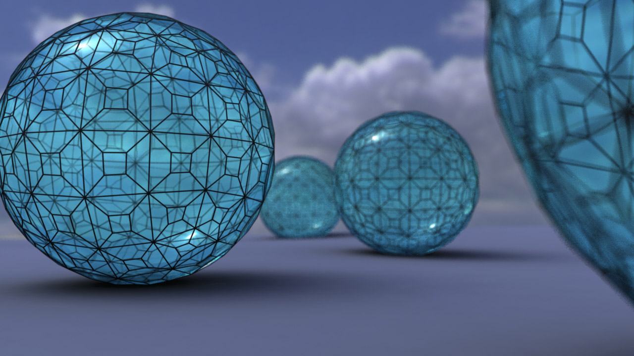
This render demonstrates the "Panes" option. The pale blue shader is created and applied to the control object upon completion of the tool, it's a simple Blinn with a refractive index of 1.4.


This has been an amazing learning experience for me. Having very little prior understanding of scripting I have been able to write this 350 line mel script, utilising all sorts of variables, functions and procedures, from scratch... and it works!!

It's certainly developed my understanding of Maya and opened up a whole new world of potential for future projects.

If you'd like to try the Lattice Tool script you can download it from here......

CLICK FOR SCRIPT - Creative Crash

10 July 2013

From Dirigibles to Lattice Tools....

After my previous posts I began to wonder what I could do next and I figured that a Zeppelin would be a cool thing to make with it's rigid skeletal structure and canvas outer... plenty of textures and materials that could interact with one another to produce some interesting simulation.

Anyway, I was thinking about how to make the rigid structure of the airship, not a particularly taxing modelling exercise but one that could be easier... something like the lattice modifier in 3DS Max would have been ideal but nothing like it exists in Maya 2013. Sure there's probably plenty of free plug ins that do the job but where's the fun in using something someone else has made when you can try and solve a problem yourself?

It was pretty straight forward to write a script that created a lattice from a poly object and it got more interesting when I decided to make the user interface for the tool, so many things to learn variables, procedures, arrays and all the other stuff that comes with programming.

I got there in the end and Lattice Tool 1.1 was born!


I'm pretty pleased by the fact that it works, there's always room for improvement, hence this being the second version and possibly not the last, but for now it gives the required results and is not confined to creating airship frameworks......


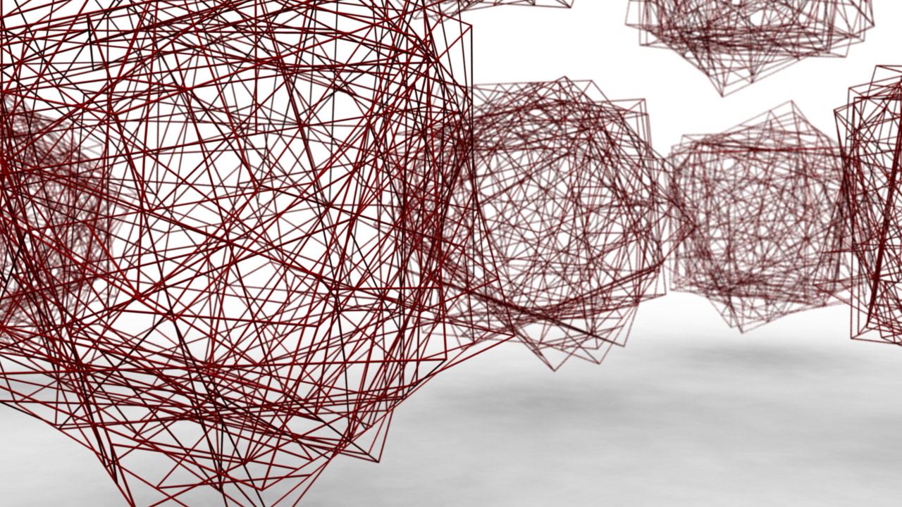
The object in the image wad created in seconds using the lattice tool on a sphere... well technically it was a smoothed cube but I'm not going to be pedantic about it! Anyway, I made the video below using many copies of the object, I'm not too sure what happened to the quality when it was compressed for Vimeo (they're usually great) but it looks a bit grainy.... oh well.


I still haven't made my airship but I'll get around to it soon enough.

30 June 2013

More Hole Than Rope........


In my previous post I started to develop my understanding of a few different systems in Maya, n-cloth, n-hair and paint effects, and I enjoyed it soooo much that I felt like running a few more tests but this time with more rope..... so I made a net.

There's twenty six ropes in the net and four tether ropes.... that's a whole load of constraints (173 to be precise) but it didn't take too long to set up and I think the effect is pretty neat... Yes I could have simply used a texture on an n-cloth plane to create a net but that's not the point of this exercise, I wanted to learn more about n-hair and this allowed me to do just that.


It's easy to see that some of the ropes don't quite reach the edge of the net, I believe that this has something to do with the stretch attribute of the hair curves... Regardless that the net is impossible I rather like the sketchy look of it but will look into fixing things in my next investigations.

The video doesn't really do justice to the amount of detail that there is in the net ropes, I left the look of them pretty loose, kind of like they were fashioned by hand from jungle vines or something similar. Here's a close up of the net that also shows the PFX mesh towards the right of the image.....


Of course, converting PFX to geometry can make for a pretty heavy scene polygon-wise, in this case the net adds up to approximately 349000 faces but it is necessary as it's the only way that Mentalray can render the paint effects strokes... It's not always necessary to render in MR but I wanted to use final gather for self shadowing in this case.

I'm really loving the unpredictability of cloth and hair simulation and I'm understanding more and more about how it is possible to control the systems and how to avoid some of the issues that can arise through using them. So it's likely that I'll be posting more investigations in the future!

22 June 2013

Full of Hot Air......

I had an idea to create an inflating object so that's just what I did.... Being a dynamic simulation though it was never going to be as straight forward as I had hoped!

My initial idea was to have a tethered balloon inflate and then the tethers release and the balloon float off.... each part is simple enough but then there's the "C" word.... that's right, I'm talking about constraints. I discovered that n-cloth doesn't play too nicely with constraints on hair systems and the only work around appeared to be to set up the hair systems first which was a bit backwards really as the n-cloth was driving the hair.

Anyway, after a little jiggery pokery I got it to work in the end.....


For a first attempt I'm pretty pleased with it, there's issues with the tension on the guy ropes and the rope on the right isn't really behaving as it ought to at it's connection with the balloon but these are minor issues thatcan be ironed out as I continue to develop my understanding of the systems, the main thing is I have created a workflow that can produce results... happy days!